Microstrip line (also known as microstrip or microstrip transmission line) is a type of electrical transmission line that is widely used in microwave applications. It is a planar structure consisting of a thin conductor strip, usually made of copper, placed on a dielectric substrate.
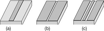
Micro-stripline is a flat strip of conducting material separated from a single grounded plane by a dielectric material as shown in fig below:

 |
| Fig: Micro-stripline |
The microstrip line is typically used for microwave frequency signals, and is commonly found in microwave circuits such as amplifiers, filters, and antennas. It can be used to transfer signals from one part of a circuit to another or to couple power into and out of a circuit.
- less expensive than traditional waveguide
- far lighter and smaller and more compact
- easy to fabricate
- easy to troubleshoot
Disadvantages:
- lower power handling capacity and higher losses comparing with waveguide
- poor isolation among adjacent lines
- unwanted radiation in uncovered configuration
- higher losses
Despite these drawbacks, microstrip line is still widely used in microwave circuits due to its low cost, low loss, and ability to be easily integrated into PCBs. Advances in technology have also led to the development of new materials and techniques that can mitigate some of the issues associated with microstrip line, making it a versatile and reliable option for many microwave applications.
