Breaking News

A Guide to Understanding Satellite Orbits and Their Types

Satellites have become an integral part of our lives, providing communication, navigation, and remote sensing services. But have you ever wondered how they orbit the Earth? In this article, we'll explore what satellite orbits are and the different types of satellite orbits.

What is a Satellite?

A satellite is a heavy object that goes around another object in space due to the effect of mutual gravitational forces. In common usage, we use the term "satellite" to refer to an artificial object launched to travel around the Earth or other planets. However, the Moon is a natural satellite of the Earth. 


What is a Satellite Orbit?

The path in which a satellite travels around the Earth in its stable condition is called a satellite orbit. The distance from the center of the Earth to the satellite is called the orbit radius, while the height of the satellite from the surface of the Earth is called altitude. At any point in the orbit, the angle of the rotation of the satellite with the horizon is referred to as inclination.


Classification of Satellite Orbits: 

Satellite orbits are characterized by three attributes: radius, altitude, and inclination. Let's explore the different types of satellite orbits based on these attributes.

1.Based on Inclination: 

According to inclination, satellite orbits are classified into three types:


   i) Equatorial orbit: The orbit whose plane coincides with the equator of the Earth is known as the equatorial orbit. Their inclination angle is zero.
  ii) Polar orbit: The orbit whose plane coincides with any polar axis of the Earth (a line passing through the reference points of the North and South poles) is known as a polar orbit. Their inclination angle is 90 degrees.
  iii) Inclined orbit: The orbit that is neither equatorial nor polar is known as an inclined orbit. Their inclination angle lies between 0 to 90 degrees.

2. Based on Radius:

Based on radius, satellite orbits are classified into two types:


   i) Circular orbit: The orbit in which the orbital radius is constant is called a circular orbit.
   ii) Eccentric orbit: The orbit in which the orbital radius is varied is called a circular orbit.

3.Based on Altitude:

Based on altitude, satellite orbits are commonly classified into three types:


   i) GEO:  Their typical altitude is above 36000 km.
   ii) MEO: Their typical altitude is from 8000 to 15000 km.
   iii) LEO: Their typical altitude is 500 to 1500 km. 

It's worth noting that there are no satellite orbits below 500 km due to Earth's atmospheric drags that create disturbances that are hard to avoid. At altitudes of 2000-5000 km and 15000-30000 km, there are belts of ionized particles known as the inner Van Allen belt and outer Van Allen belt, respectively, making satellite orbits impossible in these ranges as communication would be impossible.

4.Based on Observation Nature:

Based on observation nature, satellite orbits are classified into two types:
    i) Synchronous orbit:  An orbit in which the satellite passes every location of the Earth at the same time each day is called a synchronous orbit.
    ii) Asynchronous orbit: If a satellite is not synchronous, then it is called an asynchronous orbit.

5.Based on the Direction of Satellite Rotation:

Based on the direction of satellite rotation, satellite orbits are classified into two types:


    i) Pro-grade orbit: An orbit in which the satellite moves in the same direction as the earth's rotation is pro-grade orbit also known as direct orbit. The inclination of a pro-grade orbit always lies between 0 to 90 degree. Most of the satellites are launched in pro-grade orbit because the earths rotational velocity provides part of the orbital velocity with a consequent saving in launch energy.
    ii) Retrograde orbit:An orbit in which the satellite moves in the opposite direction as the earth's rotation is retrograde orbit. The inclination of a retrograde orbit always lies between 90 to 180 degree.


Some Special Orbits:

   Quazi zenith or figure-8 orbit: This is essentially a GEO that is inclined some 45 degree. Three satellites in this orbit provide excellent high-look angles to countries located at 45 degree latitude. This orbit is used by japan for mobile satellite communications and to provide supplemental space navigation services.
   String of pearls: It is a circular orbit in the equatorial plane but deployed in MEO rather than GEO. 6 to 8 of these satellites with similar communications capability could continuously provide service to equatorial countries where some 2 billion people live. This type of system has been proposed by the Brazilian space agency but not actually deployed. There have been proposals from Japan to create an extremely high speed orbital network via a ring of satellites that are linked together via laser-based inter-satellite connections to achieve global inter-connectivity. 


In conclusion, satellite orbits can be classified based on various parameters, including inclination, radius, altitude, observation nature, and direction of satellite rotation. Each type of orbit has its own unique characteristics and is used for different purposes, such as communication, weather monitoring, navigation, and surveillance. Understanding the different types of satellite orbits is important for designing and launching satellites, as well as for interpreting data gathered by them.

Read more ...

Understanding Source and Channel Coding for Efficient Data Transmission

Information transmission is a complex process that involves several steps, and two of the most critical steps are source coding and channel coding.

Source Coding:

Source coding is the technique used to compress the information before transmitting it over a channel to reduce the bandwidth required for transmission. The aim is to remove any redundant or unnecessary data while retaining the essential information. This process ensures the efficient utilization of resources while minimizing errors and loss of data during transmission.

There are various methods of source coding, including Huffman coding and Shannon-Fano coding, among others. Huffman coding is a popular method that assigns shorter codes to frequently occurring symbols in the data stream, reducing the overall length of the code. On the other hand, Shannon-Fano coding uses a similar approach but generates codes based on the probabilities of the symbols occurring in the data stream.

Channel Coding:

Channel coding is the process of adding extra bits to the source code to protect it from corruption during transmission. The purpose is to detect any errors that may occur and correct them at the receiver end. The extra bits added to the code are called parity bits, and they provide redundancy that enables the receiver to detect and correct errors.

Block codes and convolution codes are popular channel coding methods used to add redundancy to the transmitted data stream. Block codes divide the source data into blocks and add redundant bits to each block. Convolution codes, on the other hand, generate a continuous stream of redundant bits that are added to the source data stream.


In conclusion, source coding and channel coding are critical techniques used to ensure the efficient transmission of information over a communication channel. These methods not only reduce the bandwidth required for transmission but also protect the data from errors and corruption during transmission, ensuring the reliable delivery of information.

Read more ...

A Comparison of Amplitude Modulation and Frequency Modulation

Amplitude Modulation (AM) and Frequency Modulation (FM) are two popular techniques used to transmit  signals over long distances. 

In AM, the amplitude of the carrier wave is varied according to the amplitude of the modulating signal, whereas in FM, the frequency of the carrier wave is varied according to the amplitude of the modulating signal.

Despite their similarities, there are several differences between AM and FM. One of the most significant differences is in the fidelity of the transmitted signal. Since AM has a narrow bandwidth, it has poor fidelity, whereas FM has a wider bandwidth, resulting in better fidelity.

Another significant difference is in the efficiency of power usage. In AM, most of the power is in the carrier wave, making it less efficient, while in FM, all the transmitted power is useful. This also results in less noise interference in FM as compared to AM.

In addition, AM broadcasts operate in the medium-frequency (MF) and high-frequency (HF) ranges, while FM broadcasts operate in the high-frequency (HF) and ultra-high-frequency (UHF) ranges.

Furthermore, in AM, adjacent channel interference is a common problem due to the narrow bandwidth, whereas FM avoids adjacent channel interference due to its wide bandwidth.

Overall, while both AM and FM have their own advantages and disadvantages, FM is generally considered to be a better option for high-fidelity transmission and minimal noise interference.


Read more ...

Understanding the difference between geostationary and geosynchronous orbits

Geostationary and geosynchronous orbits are two types of orbits used by satellites orbiting the Earth. While they share some similarities, there are some distinct differences between the two. In this post, we will explore the five main differences between geostationary and geosynchronous orbits.

  • Circular vs non-circular: Geostationary orbits are circular, whereas geosynchronous orbits are not.
  • Equatorial plane vs inclined: Geostationary orbits lie in the equatorial plane and have zero inclination, while geosynchronous orbits are inclined with respect to the equatorial plane.
  • One vs many: There is only one geostationary orbit, while there can be many geosynchronous orbits.
  • Same period: Satellites in both orbits have the same period of 23 hours, 56 minutes and 4.1 seconds.
  • Stationary vs oscillating: Satellites in geostationary orbit appear stationary with respect to Earth, while satellites in geosynchronous orbit appear to oscillate with respect to a point on Earth.

Understanding the differences between these two types of orbits is important in many fields, including telecommunications and Earth observation. By knowing which type of orbit a satellite is in, we can predict its movement and ensure that it is functioning as intended.
Read more ...

Magnetic materials: Understanding their classification

Magnetic materials are materials that can produce a magnetic field or be influenced by a magnetic field. They can be naturally occurring materials, such as lodestone, or synthetic materials, such as neodymium magnets. These materials have the ability to interact with magnetic fields due to their atomic structure and/or  molecular spins . Magnetic materials are widely used in various applications such as electric motors, generators, MRI machines, and magnetic storage devices. These materials are classified into two categories based on their behaviour in a magnetic field and their applications.

According to their behaviour in a magnetic field

a) Diamagnetic materials are not magnetized in a magnetic field and do not retain any magnetic properties once the field is removed. Examples include copper, silver, gold, and bismuth.

b) Paramagnetic materials are weakly attracted by a magnetic field and exhibit temporary magnetism while in the field. Examples include aluminum, platinum, and titanium.

c) Ferromagnetic materials exhibit strong magnetism even in the absence of an external magnetic field. These materials can be magnetized and retain their magnetism after the external field is removed. Examples include iron, nickel, and cobalt.

d) Antiferromagnetic materials exhibit a magnetic ordering in which the magnetic moments of adjacent atoms align in opposite directions, resulting in zero net magnetization. Examples include chromium and manganese.

e) Ferrimagnetic materials exhibit a magnetic ordering in which the magnetic moments of adjacent atoms align in opposite directions but are not equal in magnitude, resulting in a net magnetization. Examples include magnetite and ferrites.

The first two types (dia and para) are commonly referred to as non-magnetic. They exhibit weak response to an external field. The other three are those that are commonly referred to as magnetic materials. They respond very strongly to external magnetic field and applied in wide variety of application.

Based on application

a) Hard magnetic materials are materials that retain their magnetism even in the absence of an external field, and require a large amount of energy to be demagnetized. They are used in applications where a permanent magnet is required, such as in electric motors, loudspeakers, and MRI machines. Examples include alnico, samarium cobalt, and neodymium magnets.

b) Soft magnetic materials are materials that can be easily magnetized and demagnetized, and are used in applications where the magnetic field needs to be rapidly and repeatedly switched on and off, such as in transformers, inductors, and magnetic shielding. Examples include iron-silicon alloys, nickel-iron alloys, and iron-cobalt alloys.

In summary, the classification of magnetic materials is important in understanding their behaviour in magnetic fields and their applications. Diamagnetic and paramagnetic materials are commonly referred to as non-magnetic, while ferromagnetic, antiferromagnetic, and ferrimagnetic materials are commonly referred to as magnetic materials. Hard magnetic materials retain their magnetism, while soft magnetic materials can be easily magnetized and demagnetized.
Read more ...

Magnetic materials may be hard or soft (Can you distinguish them?)

Magnetic materials are classified Based on application as :(a) Hard Magnetic Materials (b) Soft Magnetic Materials.
Difference between hard and soft magnetic materials are given below:

#Soft Magnetic MaterialsHard Magnetic Materials 
1
Soft magnetic materials are those materials which can be easily magnetized and demagnetized.
Hard magnetic materials when retaining their magnetism  are difficult to demagnetize.  
2
Loss their magnetism after the removal of the applied magnetic field
Retain their magnetism even after the removal of the applied magnetic field
3
The domain wall movement is easy
The movement of the domain wall is prevented.
4
Used for making temporary magnets
Used for making permanent magnets
5
Low hysteresis and eddy current loss due to small hysteresis area
Large hysteresis and eddy current loss due to large hysteresis loop area
6
Magnetic energy stored is less
Magnetic energy stored is high
7
Impurities decrease the strength of hard magnetic materials
Impurities increase the strength of hard magnetic materials
8
Susceptibility and permeability are high
Susceptibility and permeability are low
9
Small coercivity and retentivity values 
Large oercivity and retentivity values 
10
Hysteresis loop for a soft magnetic material is thin and long (steep curve).
Hysteresis loop for a hard magnetic material is widen
11
Examples : Soft iron, iron-Si alloys (3-4% Si), iron-cobalt-manganese alloys, Supermalloy (79% Ni-15.5% Fe-5% Mo-0.5% Mn), Permalloy (78.5% Ni-21.5% Fe etc.
Examples: steel and special alloys such as Alcomax, Alnico, and Ticonal, which contain various amounts of aluminium, nickel, cobalt, and copper etc.
12
Applications: Soft magnetic materials are used in applications requiring frequent reversal of the direction of magnetization . Commonly used in electric bell, telegraphy, relay, transformer, dynamos, diaphragms of the telephones, switching circuits, magnetic amplifiers, magnetostrictive transducers, Signal transfer, Magnetic field screening etc.   
Applications: Soft magnetic materials are used in applications requiring permanent magnets. Commonly used in Loudspeaker, Small generators, Small motors, Sensors, Video tape, Audio tape, Ferrite core memory, Drum, Hard disc, Floppy disc, Quantum devices, Data storage unit, Bubble memory etc

Read more ...

Fiber Optics: Revolutionizing Communication with its Advantages

What is fiber Optics ?

An optical fiber is a flexible and transparent fiber cable made by drawing glass (silica) or plastic to a diameter slightly thicker than a human hair. Optical fibers are used most often as a means to transmit light between the two ends of the fiber and find wide usage in fiber-optic communications, where they permit transmission over longer distances and at higher bandwidths (data rates) than wire cables. Fibers are used instead of metal wires because signals travel along them with lesser amounts of loss; in addition, fibers are also immune to electromagnetic interference, a problem from which metal wires suffer excessively.

Advantages of Optical fiber cable :

1. Wider Bandwidth : Higher information carrying capability.
2. Lower loss : Less signal attenuation over long distance.
3. Light weight: Useful where low weight is critical Le. aircraft.
4. Small size : More cables can be placed in a smaller place.
5. Strength : More stronger than electrical cables and hence can support more weight.
6. Security : Fiber-optic cables cannot be tapped as easily as electrical cables, and they do not radiate signals.
7. Interference Immunity: Fiber-optic cables do not radiate signals as some electrical cables do and cause interference to other cables. They are also immune to pick-up of interference from other sources.
8. Greater safety : Fiber-optic cables do not carry electricity. Therefore, there is no shock hazard. They are also insulators so are not susceptible to lightning strikes as electrical cables.

Optical fibers are widely used in various fields, including telecommunications, data networking, medical equipment, and aerospace. Due to their immunity to electromagnetic interference, optical fibers are an ideal solution for applications where electrical interference can cause signal distortion or loss. Overall, fiber optics is a powerful technology that has revolutionized the way we communicate and transmit information.

Read more ...

Introduction to Superconductors: Properties, Classification, and High-Temperature Superconductors

What is a superconductor? 

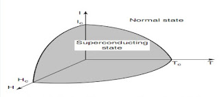
Superconductors are materials whose resistivity becomes immeasurably small or actually becomes zero below a critical temperature, Tc. For example, (La, Sr)2CuSO4 has Tc = 36K.

Factors that control superconductivity: 

Superconductivity of metals depends on current, temperature, and magnetic field properties. Superconductivity is only present when temperature, magnetic field strength, and current remain within a critical space. The relationship among these critical values is such that an increase in the critical value of one of these parameters decreases the critical value of the remaining two. Eliminating superconductivity requires increasing one of these parameters above its critical value
superconductors

Properties of superconductors:

  • Zero resistanceThe resistance of superconducting materials is zero below their critical temperature, resulting in highly efficient electrical conduction. 
  • Absence of thermoelectric effects: No Seebeck voltage, no Peltier-heat, no Thomson-heat detectable.
  • Ideal diamagnetism: Xm = -1. Superconducting materials have perfect diamagnetic properties, meaning they expel any magnetic field from their interior.
  • Meissner-effect: If a superconductor is cooled down in the presence of a weak magnetic field, below Tc, the field is completely expelled from the bulk of the superconductor.
  • Flux quantization: The magnetic flux through a superconducting ring is quantized and constant in time.
  • Critical magnetic field: The magnetic field strength that can be applied to a superconducting material without destroying its superconductivity is limited by its critical magnetic field.
  • Critical current density: The maximum current density that can be carried by a superconducting material without losing its superconductivity is known as the critical current density.
  • Critical temperature: The temperature at which a material transitions from a normal conductor to a superconductor is called its critical temperature.
  • Josephson effect: The ability of superconducting materials to produce a DC voltage across a thin insulating barrier between two superconductors, allowing for the creation of sensitive voltage sensors.

Classification of superconductors: 

According to transition period, superconductors are classified into the following two classes:

Type-1 (soft) superconductors: The superconductors which transition from a superconducting state to a normal state sharply due to any limiting parameters (especially magnetic field) are known as type-1 or soft superconductors.

Type-1 (soft) superconductors

Above figure shows the schematic representation of the resistivity of a soft superconductors when a magnetic field H is applied. These solids behave like normal conductors above Hc.

Type-II (hard)superconductors: The superconductors which transition from a superconducting state to a normal state gradually due to any limiting parameters (especially magnetic field) are known as type-II or hard superconductors.

type-II (hard)superconductors


Above figure shows the schematic representation of the resistivity of a hard superconductor when a magnetic field H is applied. The region between Hc1 and HC2 is called the vortex state in which superconducting and normal conducting areas are mixed. Above Hc2 the solid behaves like a normal conductor.

High-temperature superconductors: 

The temperature at which materials transition from a normal state to a superconducting state is called critical temperature or transition temperature. The materials having a critical temperature above 77K are known as high-temperature superconductors. They are technologically interesting because they do not require liquid helium or liquid hydrogen (-253°C) for cooling. Despite considerably higher transition temperatures, they have not yet revolutionized new technologies mainly because of their inherent brittleness, their incapability of carrying high current densities, and their environmental instability. These problems may be overcome using bismuth-based materials, composite materials, ductile substrates, silver, etc.

Read more ...

Cleanroom Technology: The Key to Contamination Control

In industries such as semiconductor manufacturing, pharmaceuticals, biotechnology, and aerospace, a clean environment is essential for successful and safe production. 
A clean room is the room in which the concentration of airborne particles is controlled to a certain level. Control of cleanliness in such a room is often achieved by controlling the introduction, formation and retention of particles and other relevant parameters (temperature, humidity and pressure) in the room. 
That area of contamination control which utilizes cleanrooms is known as cleanroom technology.

Cleanroom Construction Mechanism

The construction of a cleanroom involves several mechanisms that are designed to maintain a controlled environment. These mechanisms include:

1.Air Filtration: Supplying exceptionally large quantity of air through high efficiency filters. This helps in two senses: 
  • Extreme air dilute and remove the particles, bacteria and chemicals dispersed from personnel, machinery and other sources within the room.
  • Extreme air ensure that no dirty air flows into the cleanroom from outside by introducing pressure.
2. Building Materials: Cleanroom walls, floors, and ceilings are made of materials that do not generate particles or outgas airborne chemical contamination. Common materials used in cleanroom construction include stainless steel, laminates, and non-porous surfaces.

3. Cleanroom Clothing: Cleanroom personnel wear special clothing that envelops them and minimizes the dispersion of particles and microorganisms. Cleanroom clothing includes coveralls, hoods, gloves, and booties.

Cleanroom Practices and Protocols

In a cleanroom don’t:

  • touch your face or skin with gloves
  • touch building hardware, oily machinery, or wafer loading areas
  •  lean on equipment
  • wear cosmetics, powders, or colognes
  • wear anything on fingers-- remove all rings and bracelets
  • use paper, pencils or markers that leave dust or lint

In a cleanroom one must:
  • change gloves whenever they get dirty or torn
  • use a fresh pair of gloves whenever handling wafers
  • wipe down wafer handling areas with isopropanol
  • use clean room paper and dust-free ball point pens

Cleanrooms are critical for industries that require a controlled environment for successful and safe production. Cleanroom technology involves the construction of cleanrooms and the practices and protocols used to maintain a controlled environment. By following proper cleanroom practices and protocols, industries can reduce contamination and improve production yields.

Read more ...

Interview Questions: ECE (basic-2)

Some electronics and communication engineering basic skill topics and answers are given here:


EM waves are reflected by perfect conductors!

This is the reason why your data connection becomes slow or calls easily get disconnected while travelling in a train, lift or you are near to a big metallic body.


A signal is 'active low or high' 

In digital circuits when: A signal is 'active low' means that signal will be performing its function when its logic level is 0. A signal is 'active high' means that signal will be performing its function when its logic level is 1.


Transformer secondary winding voltage

Each coil loop of the transformer secondary produces a voltage by means of electromagnetic induction to primary winding.  As the secondary winding loops are all in series or one after one and voltages in series add, the larger number of loops produce large voltage and less number of loops produce less voltage. A easy way to understand step-up and step-down mechanism.


Flash memory

Flash memory is an electronic (solid-state) non-volatile computer storage medium that can be electrically erased and reprogrammed. Data on flash memory(thumb/pen drives and SD cards)  is erased through quantum tunneling. The most common type of flash memory in pen/thumb drives is NAND flash Flash memory which uses floating gate transistors Floating-gate MOSFET.


SEA-ME-WE 4

This stands for South East Asia–Middle East–Western Europe 4. Our entire internet is based on undersea fiber optic cables such as the SEA-ME-WE systems

Pen-drive 
If your pen drive uses FAT32 file system you cannot transfer a single file of size 4GB at a time, however you can convert the file system to NTFS and transfer a file of any size.

Mobile vibration
It's because of small dc motor. The motor that makes a phone vibrates is a stepper motor.

Music player
That what we see on our music player when we play a song is actually representation of Frequency spectra of a Tone-Frequency modulated wave! It's not there just because it looks good.

Brewster angle
The Brewster angle is the angle at which no reflection occurs in the medium of origin.


Mobile adapter
Mobile batteries require around 3.7-4.2 volts (200kHz) but our house is supplied at 230V (50kHz)  So we need a step down transformer in order to charge our mobile, which is present inside our charger. 


Did you ever notice gravel beneath around large transformers?

​​​​The main reason for this practice is actually "snakes".  Large transformers produce substantial vibrations due to magneto-striction which get transmitted to ground. Due to this effect the transformers placed on solid ground attract snakes. To prevent this, transformers are surrounded by gravel which prevents snakes from coming near it.

Shockwave
The shockwave during rain has a voltage as high as 50k–80k or even 1Lakh Volts. The ground has potential of 0 Volts. Thus there is a huge potential difference between cloud and ground and thus this makes even air as conductive material. By nature electric current follows the shortest and simplest path to flow and thus it flows through whatever taller conductive material present around to reach upto the ground. That’s why in urban areas most of the shockwaves fall on industrial chimneys or coconut trees which attain a great height in the surroundings. That’s why one shouldn’t walk around in an open park or field or stream through water bodies during heavy lightining.


The height at which a wire is suspended is related to the voltage it has.
The inter-district transmission lines carrying around 33,000 V are placed the highest. They're usually seen near a power house (regional distribution centres) and are quite thick. The next in height are the 11,000 V lines, placed at about 23-26 ft. They supply high electricity to local transformers which finally step down the voltage to 230 V (or 110 V in some places like America and Canada).At the lowest height are the 230 V lines, from which the service drops are made. 11000 V is stepped down to 400 V (Phase to Phase). There are 3 wires, carrying 3 different phases of electricity. Any one of the three phases and a neutral is supplied to the house, powering the appliances at 230 volts.

Electric bulb blinking
In AC power, the direction of the current flowing is continuously changing. filament bulb only glows on one direction of power flow.  So, the bulb continuously blinks. Human eyes can't make out that it is blinking because the frequency is 50 times per second or 50hz.

Flow of current
Current does not flow from positive to negative or vice versa, it flows in a continuous loop. By convention, from Ben Franklin, current is defined to flow from negative to positive inside a battery or power supply, and from positive to negative in the circuit outside a power supply.  Current is not really the movement of electrons, they actually move quite slowly. The electrons in the electrical wire going to your blow dryer travel at about 1 inch per minute. The electrical current flows at close to the speed of light.
Read more ...

Assembly language Programming Codes for the 8086 Microprocessor

Assembly language is a low-level programming language that is used to write software that can be executed directly by a computer's central processing unit (CPU). It is particularly useful for programming microprocessors, such as the 8086 microprocessor.

In order to write effective assembly language programs for the 8086 microprocessor, it is essential to have a deep understanding of the internal structure of the processor itself. This knowledge allows you to write code that makes efficient use of the processor's capabilities and can be optimized for speed and performance.

Fortunately, there are a variety of resources available to help you learn assembly language programming for the 8086 microprocessor. One useful starting point is the Microsoft Macro Assembler (MASM), which is a popular assembler used for programming on the x86 architecture.
To help you get started with MASM, we've provided some sample codes below that you can use for practice:

Code-1: Print a message 'hello world'

.MODEL SMALL
.STACK 100H

.DATA
MSG DB 'HELLO WORLD!$'

.CODE
MAIN PROC

MOV AX,@DATA
MOV DS,AX

LEA DX,MSG
MOV AH,9
INT 21H

MOV AH,4CH
INT 21H


MAIN ENDP
END MAIN 
...................................................

Code-2: Print all the ASCII symbols from 0 to 256

.MODEL SMALL
.STACK 100H

.CODE
MAIN PROC

MOV AH,2
MOV CX,256
MOV DL,0

PRINT_LOOP:
INT 21H
INC DL
DEC CX
JNZ PRINT_LOOP 


MOV AH,4CH
INT 21H 


MAIN ENDP
END MAIN 
.................................................

Code-3: Convert a lowercase letter into uppercase


.MODEL SMALL
.STACK 100H
.DATA
MSG1 DB 'ENTER THE LOWERCASE LATTER:$'
MSG2 DB 'CORRESPONDING UPPERCASE LATTER IS:'
CHAR DB ? , '$'
.CODE
MAIN PROC

MOV AX,@DATA
MOV DS,AX

LEA DX,MSG1
MOV AH,9
INT 21H

MOV AH,1
INT 21H

SUB AL,20H 
MOV CHAR,AL

LEA DX,MSG2
MOV AH,9
INT 21H

MOV AH,4CH
INT 21H 


MAIN ENDP
END MAIN 
......................................................

Code-4: Convert an uppercase letter into lowercase 


.MODEL SMALL
.STACK 100H
.DATA
MSG1 DB 'ENTER THE UPPERCASE LATTER:$'
MSG2 DB 'CORRESPONDING LOWERCASE LATTER IS:'
CHAR DB ? , '$'
.CODE
MAIN PROC

MOV AX,@DATA
MOV DS,AX

LEA DX,MSG1
MOV AH,9
INT 21H

MOV AH,1
INT 21H

ADD AL,20H 
MOV CHAR,AL

LEA DX,MSG2
MOV AH,9
INT 21H

MOV AH,4CH
INT 21H 


MAIN ENDP
END MAIN 
......................................................

Code-5: Addition of two numbers


.MODEL SMALL
.STACK 100H

.DATA 
MSG1 DB 10,13,'ENTER YOUR FIRST NUMBER:$'
MSG2 DB 10,13,'ENTER YOUR SECOND NUMBER:$'
MSG3 DB 10,13,'ADD=$'
N1 DB ?
N2 DB ?
RE DB ?

.CODE 
MAIN PROC

MOV AX,@DATA
MOV DS,AX

LEA DX,MSG1
MOV AH,9
INT 21H

MOV AH,1
INT 21H

SUB AL,30H
MOV N1,AL

LEA DX,MSG2
MOV AH,9
INT 21H

MOV AH,1
INT 21H

SUB AL,30H
MOV N2,AL

MOV AL,N1
ADD AL,N2
MOV RE,AL

ADD AH,30H
ADD AL,30H
MOV BX,AX

LEA DX,MSG3
MOV AH,9
INT 21H

MOV AH,2
MOV DL,BH
INT 21H
MOV AH,2 
MOV DL,BL
INT 21H

MOV AH,4CH
INT 21H

MAIN ENDP
END MAIN
........................................................

Code-6: Multiplication of two numbers

.MODEL SMALL
.STACK 100H
.DATA
NUM1 DB ?
NUM2 DB ? 
RESULT DB ?
MSG1 DB 10,13,'ENTER FIRST NUMBER: $' 
MSG2 DB 10,13,'ENTER SECOND NUMBER: $' 
MSG3 DB 10,13,'AFTER MULTIPLYCATION RESULT IS: $' 
.CODE
MAIN PROC

MOV AX,@DATA
MOV DS,AX

LEA DX,MSG1
MOV AH,9
INT 21H

MOV AH,1
INT 21H
SUB AL,30H
MOV NUM1,AL

LEA DX,MSG2
MOV AH,9
INT 21H

MOV AH,1
INT 21H
SUB AL,30H
MOV NUM2,AL

MUL NUM1

MOV RESULT,AL
AAM

ADD AH,30H
ADD AL,30H

MOV BX,AX

LEA DX,MSG3
MOV AH,9
INT 21H

MOV AH,2
MOV DL,BH
INT 21H 

MOV AH,2
MOV DL,BL
INT 21H

MOV AH,4CH
INT 21H 

MAIN ENDP
END MAIN 
.....................................................

Code-7: Taking input a string

.MODEL SMALL
.STACK 100H
.DATA
STRING DB ?
EXT DB '$'
MSG DB 10,13,'ENTER STRING $' 
.CODE
MAIN PROC

MOV AX,@DATA
MOV DS,AX

LEA DX,MSG
MOV AH,9
INT 21H

LEA SI,STRING

INP:
MOV AH,1
INT 21H
MOV [SI],AL
INC SI

CMP AL,0DH
JNZ INP

MOV [SI],'$'
LEA DX,STRING
MOV AH,9
INT 21H 

MOV AH,4CH
INT 21H 

MAIN ENDP
END MAIN 
......................................................

Code-8: Reverse a string


.MODEL SMALL
.STACK 100H 
.CODE
MAIN PROC

MOV AH,2
MOV DL,'?'
INT 21H

XOR CX,CX
MOV AH,1
INT 21H

WHILE_:
CMP AL,0DH
JE END_WHILE

PUSH AX
INC CX

INT 21H
JMP WHILE_

END_WHILE:
MOV AH,2
MOV DL,0DH
INT 21H
MOV DL,0AH
INT 21H
JCXZ EXIT

TOP:
POP DX
INT 21H
LOOP TOP
EXIT: 
MOV AH,4CH
INT 21H 

MAIN ENDP
END MAIN
...................................................

Code-9: Determine prime number

.MODEL SMALL
.STACK 100H
.DATA
NUM DB ?
MSG1 DB 10,13,'ENTER NO: $' 
MSG2 DB 10,13,'NOT PRIME: $' 
MSG3 DB 10,13,'PRIME $' 
.CODE
MAIN PROC

MOV AX,@DATA
MOV DS,AX

LEA DX,MSG1
MOV AH,9
INT 21H

MOV AH,1
INT 21H
SUB AL,30H
MOV NUM,AL

CMP AL,1
JLE LBL2
MOV AH,00
CMP AL,3
JLE LBL3
MOV AH,00

MOV CL,2
DIV CL
MOV CL,AL

LBL1:
MOV AH,00
MOV AL,NUM
DIV CL
CMP AH,00
JZ LBL2
DEC CL
CMP CL,1
JNE LBL1
JMP LBL3
LBL2:
MOV AH,9
LEA DX,MSG2
INT 21H
JMP EXIT
LBL3:
MOV AH,9
LEA DX,MSG3
INT 21H
EXIT:
MOV AH,4CH
INT 21H 

MAIN ENDP
END MAIN 

By studying and practicing with examples such as these, you can develop a strong foundation in assembly language programming and become proficient in programming the 8086 microprocessor. Good luck!
Read more ...

Interview Questions: ECE (basic-1)


electronics and communication engineering

Some electronics and communication engineering basic skill topics and answers are given here.............


Electron

Nobody knows the shape, size, or just about anything about electrons besides their charge and mass. We do know they're very, very small. How small? So small we can't measure their diameter, we can only say they're smaller than some upper bound.

Flat channel
A channel which passes all spectral components with approximately equal gain and linear phase.

Co-channel interference
Frequency reuse implies that in a given coverage area there are several cells that use the same set of frequencies. These cells are called co-channel cells and the interference between signals from these cells is called co-channel interference.


Adjacent channel interference

Interference resulting from signals which are adjacent in frequency to the desired signal is called adjacent channel interference. Adjacent channel interference can be minimized through careful filtering and channel assignments. 

What is inter-modulation noise?
When a signal (having different frequency components) passes through a transmitting media, then due to non-linearity, some of the frequency components may combine to generate a different frequency component. This leads to distortion in the signal, which is known as inter-modulation noise. For example, a signal may be having frequency components fx and fyand due to non-linearity of the media they may generate a frequency component (fx+fy). Further a frequency of (fx+fy) may be already present in the original signal. This causes inter-modulation noise.

Major impacts on electromagnetic wave propagation
Reflection, diffraction, and scattering are the three basic propagation mechanisms which impact propagation in a mobile communication system.

       Reflection occurs when a propagating electromagnetic wave impinges upon an object which has very large dimensions when compared to the wavelength of the propagating wave. Reflections occur from the surface of the earth and from buildings and walls.

       Diffraction occurs when the radio path between the transmitter and receiver is obstructed by a surface that has sharp irregularities (edges). The secondary waves resulting from the obstructing surface are present throughout the space and even behind the obstacle, giving rise to a bending of waves around the obstacle, even when a line-of-sight path does not exist between transmitter and receiver.

       Scattering occurs when the medium through which the wave travels consists of objects with dimensions that are small compared to the wavelength and where the number of obstacles per unit volume is large. Scattered waves are produced by rough surfaces, small objects, or by other irregularities in the channel. In practice, foliage, street signs, and lamp posts induce scattering in a mobile communications system.

Relation between EM waves & perfect conductor
Since electromagnetic energy cannot pass through a perfect conductor a plane wave incident on a conductor has all of its energy reflected.

How the effect of delay distortion can be minimized?
Ans: Delay distortion can be minimized by using an equalizer (a kind of filter). Delay distortion arises because different frequency components of the signal suffer different delay as the signal passes through the media. This happens because the velocity of the signal varies with frequency and it is predominant in case of digital signals.

What is Fading?
Fading is used to describe the rapid fluctuation of the amplitude of a radio signal over a short period of time or travel distance so that large-scale path loss effects may be ignored. Fading is caused by interference between two or more versions of the transmitted signal which arrive at the receiver at slightly different times. These waves called multi-path waves, combine at the receiver antenna to give a resultant signal which can vary widely in amplitude and phase, depending on the distribution of the intensity and relative propagation time of the waves and the bandwidth of the transmitted signal.

Why is it necessary to limit the band of a signal before performing sampling?
It is necessary to limit the bandwidth of a signal before sampling so that the basic requirement of sampling theorem ( the sampling rate should twice or more than twice the maximum frequency component of the signal ) is satisfied. This is known as Nyquist rate. If it is violated, original signal can not be recovered from the sampled signal.

Coherent and non-coherent demodulation
Demodulation techniques may be broadly divided into two categories: coherent and non-coherent demodulation. Coherent demodulation requires knowledge of the transmitted carrier frequency and phase at the receiver whereas non-coherent detection requires no phase information. 

Between AM and FM, which one gives better noise immunity?
FM is more immune to noise than AM, since the power of transmission is independent of the modulation index.

Why do you need encoding of data before sending over a medium?
Suitable encoding of data is required in order to transmit signal with minimum attenuation and optimize the use of transmission media in terms of data rate and error rate.

Between RZ and NRZ encoding techniques, which requires higher bandwidth and why?
RZ encoding requires more bandwidth, as it requires two signal changes to encode one bit.

Generation of FM
There are basically two methods of generating an FM signal: the direct method and the indirect method. In the direct method, the carrier frequency is directly varied in accordance with the input modulating signal. In the indirect method, a narrow-band FM signal is generated using a balanced modulator and  frequency multiplication is used to increase both the frequency deviation and the carrier frequency to the required level.

Performance of a modulation scheme
The performance of a modulation scheme is often measured in terms of its power efficiency and bandwidth efficiency. Power efficiency describes the ability of a modulation technique to preserve the fidelity of the digital message at low power levels. Bandwidth efficiency describes the ability of a modulation scheme to accommodate data within a limited bandwidth. 

Nyquist caiteria
Nyquist was the first to solve the problem of overcoming inter-symbol interference while keeping the transmission bandwidth low . He observed that the effect of ISI could be completely nullified if the overall response of the communication system (including transmitter, channel and receiver) is designed so that at every sampling instant at the receiver, the response due to all symbols except the current symbol is .equal to zero.

What  is inside of fan regulator ?
It is TRIAC. It is a power-electronic device which changes the firing angle to get different voltage and that’s how we control our fan.

Over voltage is dangerous!
In case over-voltage occurs in a house , all your electrical equipment will get burned if they are in ON position. Electrical equipments are protected by MCBs (or fuses) only from short-circuits and over-loading and not from Over-voltage.The one way to control and prevent this is by installing an auto-cut voltage regulator in the main supply of the house.Over-voltage gets introduced in distribution power lines from sub-stations side in case over voltage relays installed in sub-stations fail to operate for some reason.

Transformer is only for AC
If you will supply a transformer with a battery (dc voltage source), u will end up burning the windings of transformer. Larger the size of transformer, larger the time it will take.

Electronic device don't get damaged via overcharging!
That your phone/laptop battery will not get damaged if you still have the device connected to charging even after reaching 100%. Because the internal circuitry in the devices will prevent overcharging. 

AC versus DC
AC is more efficient for transmission, but can't be stored as AC;  and DC  can be stored in batteries but is not efficiently transmitted.

Current is cut!
Generally we use to say 'current is cut', which is technically wrong. We cannot cut current. It should be 'power cut'.

Some multi-conductor transmission cables are twisted. why?
Instrumentation cables are twisted. (Twisted pair ). This twisting is done to cancel out the electromagnetic interference between the two.

What do you mean by Corona ?
Voltage between transmission lines is so high that it can cause partial breakdown of the air surrounding it, which results in a colorful field and a hissing noise called corona.


Read more ...
Designed By